
Multi-projection Wizard
This manual will guide you through the process of connecting two or many projectors into a seamless screen.
This functionality requires the Group of Projectors created.
How to connect the image from two projectors into a single screen?
There are two basic methods of blending images.
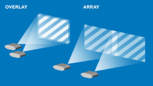
The simple method of connecting an image from multiple projectors is called Overlay
Overlay increases the Illuminance of the projection. With the Overlay method, you simply use Editor to mapp the same Objects on top of each other. You don’t need Edge Blending for that.
Note: When performing Overlay it may help to activate the Outlines Forever function. With the Outlines Forever activated, it will be easier for you to fit the Objects’ frames on top of each other. (Lumiverse UI/Settings/Editor Settings/Outlines Forever)
The more complex method of connecting images from multiple projectors is called Array
With the Array Method, more projector images are welded together into a single screen. A certain Edge Overlap (typically around 5-15%) is used on the edges to enable for very smooth image seam.
How to connect an image from multiple projectors in an Array?
– First, access the Group Control and switch the Group to ON state
– Use Group Control to Create a New Project
– Switch the Group to the New Project
– Now, leave the Group Control and Access each projectors’ UI and follow this set of steps:
– Activate the Outlines Forever function. (Lumiverse UI/Settings/Editor Settings/Outlines Forever)
– Navigate to Editor
– Add Object (+), Apps </>, Tools folder, Solid
– Select Solid in Editor, select Edit Object, select Editor Symbol Tab, select Fit To Screen
– Select Solid in Editor, select Edit Object, and set Solid to grey (RGB 120, 120, 120)
– Select Solid in Editor, select Edit Object, navigate to Filters, select Add Filter (+), and select Multicanvas Filter.
– Repeat this for all projectors in the Group.
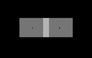
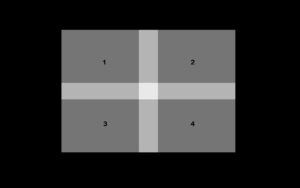
Now, with all projectors projecting grey rectangles in the full screen you should physically organize (tilt, move, rotate, zoom) the projectors to fully illuminate desired surfaces. You can organize projectors into Rows, Columns, or Rectangles. Tetris-like shapes are not supported. We recommend an edge overlap of around 5-15%. Fix the projectors in place.
Access the Editor of any projector member of the Group and select the Solid object and select Edit Object. Navigate to Filters, open the Multicanvas filter sub-menu (three dots) and select Edit Filter. This is where you control the Multicanvas Filter. First, we need to create a new Topology. Topology is like a sub-group. It allows you to create separate sub-screens in larger groups. For the purpose of this manual, we will only work with a single topology. (If your project contains multiple topologies, complete one topology first. After you complete the first topology, complete the next topology, etc.) Create a new topology and give it a name. The topology will appear as a new item under the Topology Tab. Now, you need to access the Multicanvas Filter in all projectors in the Group and connect each projector to the newly created topology. When adding projectors to the topology, a matrix of (+) buttons will appear around the device number. You need to select the appropriate (+) button so that the physical position of the projectors corresponds with the visualized scheme in the Multicanvas Filter.
Once you finish adding projectors to the topology, you need to align all Solid Objects in the Editor to form a perfect rectangle. Use corner dragging and adjust the perspective deformation of Solid Objects in each projector’s Editor to form a perfect rectangle with 90 degrees angles and precise edge alignment. Use Editor/Edit/Precise Mapping Tool to select individual corners and move them precisely with arrow buttons. When done, you may use Editor/Edit/Lock Position to lock object corners’ positions in place. (NOTE: If you want to use the multiscan feature, don’t use the mesh warp or bezier warp for these adjustments.)
When you finish aligning objects, you may proceed to the next step, called Edge Overlap. This has to be done for all projectors in the Group. Select the Solid Object in the Editor, hit Edit Object, navigate to Filters, open the sub-menu in the Multicanvas item (three dots), select Edit, and open the Edge Overlap Tab. There is a slider (s) controlling the position of a black line, projected over the white surface. Use the Edge Overlap slider to position the black line precisely on the edge of the neighbor projector. If the lines are not parallel, switch back to Editor and adjust the position of the Solid Object corners to fine-tune the geometry. Then navigate to the Multicanvas Filter and adjust the Edge Overlap slider to perfect alignment with the edge. The edge of the neighbor projector should be in the middle of the Edge Overlap black line. Repeat this with all projectors in the Group.
Once you have all Edge Overlap lines aligned to neighbor projector edges, you can test the set-up with an image or video of your choice. Select Solid Object in Editor, hit Edit Object, navigate to Editor Symbol Tab, and select Change Source. Locate your desired media source and do this for all projectors in the Group. After this step, you will see your image well overlapped. If you experience imperfections, you need to improve the alignment of the Objects in Editor or you need to fine-tune the Edge Overlap parameter within the Multicanvas Filter.
Once you are happy with the geometry of the resulting image, you can proceed to Edge Blending. Select the Object in Editor, hit Edit, navigate to Filters, open the Multicanvas Fitler sub-menu (three dots), and change the Multicanvas Filter Mode from Adjustment to Blending. Repeat for all projectors. Use the Gamma slider (Multicanvas Filter) to fine-tune the blend curve.
Disable the Outlines Forever feature in Settings/Editor Settings to hide the white frame line.